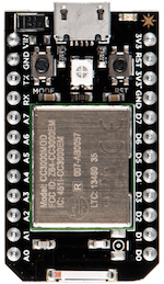
Meet the Spark Core

The spark core is a prototyping tool for creating internet of things devices.
The core comes with a wifi antenna built right in so that connecting your creation to the interent is a cinch.
Parts of the Spark Core
LEDs
The Spark Core has 2 LEDs on it. One is a larger RGB LED which is used to indicate
the status of your Spark. The other is a smaller blue LED which turns on and off
when you turn the D7 to HIGH or LOW respectively.
More information about the Spark Core LEDs can be found on the Spark Docs website
Buttons
In addition to the two LEDs the Spark Core also has two buttons. Unlike the the LEDs the two buttons are the same size. They are labeled RESET and MODE.
When holding the Spark Core with the mini USB port pointing up you will see the RESET button on the right side of the spark and the MODE button on the left.
RESET
The RESET button effectively depowers and repowers the microcontroller. This is an effective way to easily restart the application running on your Spark without having to unplug the Spark from it’s power source.
MODE
The MODE button has thee functions.
From the Spark Docs
Hold down the MODE button for three seconds to put the Core into Smart Config mode to connect it to your local Wi-Fi network. The LED should start flashing blue.
Hold down the MODE button for ten seconds to clear the Core’s memory of Wi-Fi networks.
Hold down the MODE button, tap on the RESET button and wait for three seconds to enter Bootloader mode, where you can reprogram the Core over USB or JTAG. Release the MODE button when you see the LED flashing yellow. If you do this by accident, simply hit RESET button to leave Bootloader mode.
Hold down the MODE button, tap once on the RESET button and wait for ten seconds to do a Factory Reset, where the Core is reprogrammed with the software that was installed on the Core in the factory (the Tinker application). The LED should turn white for three seconds and begin flashing quickly; when the LED switches to another color the Core has been reset. This is useful if you encounter bugs with your firmware, or if you just want to get back to Tinker.
Pins
You may have also noticed the 24 pins coming out of your Spark Core. These pins are labeled:
-
VIN
The
VINpin is used to power your Spark from a unregulated power source with a voltage between 3.6V and 6V. If you are using USB to power your Spark then this pin can be used as aV V~OUTto power external components.Avoid powering the Core via USB and V~IN~ concurrently
-
3V3
This pin outputs a regulated 3.3V power rail that can be used to power any components.
Also, if you have your own 3.3V regulated power source, you can plug it in here to power the Core.
-
3V3*
This is a separate low-noise regulated 3.3V power rail designed for analog circuitry that may be susceptible to noise from the digital components. If you’re using any sensitive analog sensors, power them from 3V3* instead of from 3V3.
-
!RST
You can reset your Core (same as pressing the RESET button) by connecting this pin to
GND. -
GND
Ground pins.
-
D0 to D7
These pins are the general purpose Digital input/output pins. Because these pins are digital that means that they cannot read the values from analog sensors.
-
A0 to A7
Like D0-D7 these pins are general purpose input/output pins, but unlike their digital counterparts these pins are Analog.
-
TX and RX
These pins are for communicating over Serial/UART. TX represents the transmitting pin, and RX represents the receiving pin.
More information about the Spark Core pins is available form the Spark Docs at http://docs.spark.io/start/#pins.
Time To Connect!
Now that you have either taken the time to familiarize yourself with your Spark Core (or scrolled down to the bottom of this page) it’s now finally time to connect to your Spark!